Summary
In the previous tutorial, we built a minimal Direct3D 11 application that outputs a single color to the window.
이전 튜토리얼에서, 우리는 화면을 단일 색상으로 채워 출력하는 간단한 Direct3D 11 실행프로그램을 만들었다.
In this tutorial, we will extend the application to render a single triangle on the screen.
이 튜토리얼에서, 우리는 단일 삼각형을 화면에 그리도록 실행프로그램을 확장할 것이다.
We will go through the process to set up the data structures associated with a triangle.
우리는 삼각형과 관련된 자료 구조체를 설정하는 과정을 살펴볼 것이다.
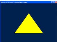
The outcome of this tutorial is a window with a triangle rendered to the center of the window.
이 튜토리얼의 결과물은 화면 정중앙에 삼각형을 렌더링하는 것이다.
Source
(SDK root)\Samples\C++\Direct3D11\Tutorials\Tutorial02
Elements of a Triangle
A triangle is defined by its three points, also called vertices.
삼각형은 정점이라 불리는 세 개의 점으로 정의된다.
A set of three vertices with unique positions define a unique triangle.
세 개의 고유한 위치를 지닌 정점들의 집합은 하나의 고유한 삼각형을 정의한다.
In order for a GPU to render a triangle, we must tell it about the position of the triangle’s three vertices.
GPU가 삼각형을 렌더링하기 위해서는, GPU에게 삼각형의 세 정점의 위치를 전달해야 한다.
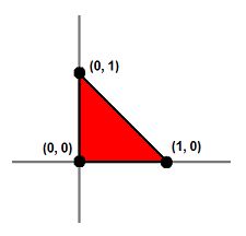
For a 2D example, let’s say we wish to render a triangle such as that in figure 1.
2차원 공간에 관한 예시로, 그림 1에 있는 삼각형을 렌더하고자 한다고 가정해보자.
We would pass three vertices with the positions (0, 0) (0, 1) and (1, 0) to the GPU, and then the GPU has enough information to render the triangle that we want.
우리는 (0, 0) (0, 1) (1, 0) 위치에 있는 세 점점을 GPU에 전달한다. 그러면 GPU는 삼각형을 렌더하기 위한 충분한 정보를 가진다.
Figure 1. A triangle in 2D defined by its three vertices
그림 1. 세 개의 정점으로 정의된 2차원 삼각형
So now we know that we must pass three positions to the GPU in order to render a triangle.
이제 GPU에 삼각형의 세 점의 정보를 넘겨야 한다는 사실을 알았을 것이다.
How do we pass this information to the GPU?
어떻게 이 정보들을 GPU에 넘길 수 있을까?
In Direct3D 11, vertex information such as position is stored in a buffer resource.
Direct3D 11에서, 위치와 같은 정점 정보는 버퍼 리소스에 저장된다.
A buffer that is used to store vertex information is called, not surprisingly, a vertex buffer.
정점 정보를 저장하기 위한 버퍼는, 예상했듯이, 정점 버퍼로 불린다.
We must create a vertex buffer large enough for three vertices and fill it with the vertex positions.
정점 버퍼는 세 개의 삼각형을 저장하기에 충분한 크기로 생성되어야 하며 정점 정보로 채워져야 한다.
In Direct3D 11, the application must specify a buffer size in bytes when creating a buffer resource.
Direct3D 11에서, 실행프로그램은 버퍼 리소스를 생성할 때 바이트 단위로 버퍼의 크기를 특정해야 한다.
We know the buffer has to be large enough for three vertices, but how many bytes does each vertex need?
버퍼가 세 개의 정점을 담을 사이즈여야 한다는 것을 알겠는데, 그래서 각 정점은 몇 바이트를 차지하는가?
To answer that question requires an understanding of vertex layout.
이 질문에 답변하기 위해선 정점 레이아웃에 대한 이해가 선행되어야 한다.
Input Layout
A vertex has a position.
정점은 위치 정보를 가진다.
More often than not, it also has other attributes as well, such as a normal, one or more colors, texture coordinates (used for texture mapping), and so on.
대부분의 경우, 정점은 위치 외에도 법선, 하나 이상의 색상, 텍스처 좌표(텍스처 매핑에 사용됨) 등과 같은 다른 속성들도 함께 가진다.
Vertex layout defines how these attributes lie in memory: what data type each attribute uses, what size each attribute has, and the order of the attributes in memory.
정점 레이아웃은 이러한 특성 정보들이 어떠한 방식으로 메모리에 위치하는지를 정의한다: 각각의 특성들이 어떠한 자료형을 사용하는지, 각 특성의 크기는 얼마인지, 그리고 특성들은 어떠한 순서로 정렬되는지 등등.
Because the attributes usually have different types, similar to the fields in a C structure, a vertex is usually represented by a structure.
보통 속성들은 서로 다른 타입이기 때문에, C 구조체의 필드들처럼, 정점은 보통 구조체로 표현된다.
The size of the vertex is conveniently obtained from the size of the structure.
정점의 크기는 구조체의 크기로부터 적절히 얻어질 수 있다.
In this tutorial, we are only working with the position of the vertices.
이 튜토리얼에서, 우리는 정점의 위치만을 가지고 작업한다.
Therefore, we define our vertex structure with a single field of the type XMFLOAT3.
그러므로, 우리는 정점을 XMFLOAT3 타입의 단일 필드만 가진 구조체로 정의한다.
This type is a vector of three floating-points components, which is typically the data type used for position in 3D.
이 타입은 세 개의 부동소수점 요소들의 벡터로, 일반적으로 3D 공간에서 위치를 표현할 때 사용하는 데이터 타입이다.
struct SimpleVertex
{
    XMFLOAT3 Pos;  // Position
};
We now have a structure that represents our vertex.
이제 정점을 나타내는 구조체를 얻었다.
That takes care of storing vertex information in system memory in our application.
이 구조체를 사용하여 정점 정보를 응용프로그램의 시스템 메모리에 저장할 수 있다.
However, when we feed the GPU the vertex buffer containing our vertices, we are just feeding it a chunk of memory.
하지만, 우리가 정점을 저장하고 있는 정점 버퍼를 GPU에 제공할 때, 우리는 단지 메모리 덩어리를 제공하는 것이다.
The GPU must also know about the vertex layout in order to extract correct attributes out from the buffer.
GPU는 정확한 속성을 버퍼로부터 추출하기 위해서 정점 레이아웃에 관해서도 알아야 한다.
To accomplish this requires the use of an input layout.
이 작업을 수행하려면 입력 레이아웃을 사용해야 한다.
In Direct3D 11, an input layout is a Direct3D object that describes the structure of vertices in a way that can be understood by the GPU.
Direct3D 11에서, 입력 레이아웃은 GPU가 읽을 수 있는 방식으로 정점 구조체를 정의하는 Direct3D 객체이다.
Each vertex attribute can be described with the D3D11_INPUT_ELEMENT_DESC structure.
각 정점 특성은 D3D11_INPUT_ELEMENT_DESC 구조체에 의해 정의된다.
An application defines an array of one or more D3D11_INPUT_ELEMENT_DESC, then uses that array to create the input layout object which describes the vertex as a whole.
응용프로그램은 하나 또는 그 이상의 D3D11_INPUT_ELEMENT_DESC를 정의하며, 그 배열을 사용해 정점 전체를 정의하는 입력 레이아웃 객체를 생성한다.
We will now look at the fields of D3D11_INPUT_ELEMENT_DESC in detail.
D3D11_INPUT_ELEMENT_DESC의 필드들을 세부적으로 살펴보자.
SemanticName
의미론적인 이름
Semantic name is a string containing a word that describes the nature or purpose (or semantics) of this element.
Semantic name은 해당 요소의 본질이나 목적(또는 의미론)을 설명하는 단어를 포함하는 문자열이다.
The word can be in any form that a C identifier can, and can be anything that we choose.
그 단어는 C 식별자가 될 수 있는 어떤 형태라도 가능하며, 우리가 선택하는 어떤 것이든 될 수 있다.
For instance, a good semantic name for the vertex’s position is POSITION. Semantic names are not case-sensitive.
예를 들어, 정점의 위치에 대한 좋은 의미론적 이름은 POSITION이다. 의미론적 이름은 대소문자를 구분하지 않는다.
SemanticIndex
의미론적 인덱스
Semantic index supplements semantic name.
의미론적 인덱스는 의미론적 이름(semantic name)을 보충한다.
A vertex may have multiple attributes of the same nature.
하나의 정점은 동일한 성격의 여러 특성을 가질 수 있다.
For example, it may have 2 sets of texture coordinates or 2 sets of colors.
예를 들어, 정점은 두 세트의 텍스처 좌표 또는 두 세트의 색상을 가질 수 있다.
Instead of using semantic names that have numbers appended, such as “COLOR0” and “COLOR1”, the two elements can share a single semantic name, “COLOR”, with different semantic indices 0 and 1.
“COLOR0”과 “COLOR1”처럼 숫자가 덧붙여진 의미론적 이름을 사용하는 대신, 두 요소는 “COLOR”라는 단일 의미론적 이름을 공유하고, 각각 0과 1의 다른 의미론적 인덱스를 가질 수 있다.
Format
형식
Format defines the data type to be used for this element.
형식은 요소를 표현하기 위해 사용할 자료형을 정의한다.
For instance, a format of DXGI_FORMAT_R32G32B32_FLOAT has three 32-bit floating point numbers, making the element 12-byte long.
예를 들어, DXGI_FORMAT_R32G32B32_FLOAT 형식은 세 개의 32비트 부동 소수점 숫자를 가지므로, 이 요소의 길이는 12바이트가 된다.
A format of DXGI_FORMAT_R16G16B16A16_UINT has four 16-bit unsigned integers, making the element 8 bytes long.
DXGI_FORMAT_R16G16B16A16_UINT 형식은 네 개의 16비트 부호 없는 정수를 가지므로, 이 요소의 길이는 8바이트가 된다.
InputSlot
입력 슬롯
As mentioned previously, a Direct3D 11 application passes vertex data to the GPU via the use of vertex buffer. In Direct3D 11, multiple vertex buffers can be fed to the GPU simultaneously, 16 to be exact. Each vertex buffer is bound to an input slot number ranging from 0 to 15. The InputSlot field tells the GPU which vertex buffer it should fetch for this element.
앞서 언급했듯이, Direct3D 11 애플리케이션은 정점 버퍼를 사용하여 GPU에 정점 데이터를 전달한다. Direct3D 11에서는 여러 개의 정점 버퍼를 동시에 GPU에 공급할 수 있는데, 정확히는 16개이다. 각 정점 버퍼는 0부터 15까지의 입력 슬롯 번호에 바인딩된다. InputSlot 필드는 GPU에 이 요소를 위해 어떤 정점 버퍼를 가져와야 하는지 알려준다.
AlignedByteOffset
정렬된 바이트 오프셋
A vertex is stored in a vertex buffer, which is simply a chunk of memory. The AlignedByteOffset field tells the GPU the memory location to start fetching the data for this element.
정점은 단순히 메모리 덩어리인 정점 버퍼에 저장된다. AlignedByteOffset 필드는 GPU에 이 요소에 대한 데이터를 가져오기 시작할 메모리 위치를 알려준다.
InputSlotClass
입력 슬롯 클래스
This field usually has the value D3D11_INPUT_PER_VERTEX_DATA. When an application uses instancing, it can set an input layout’s InputSlotClass to D3D11_INPUT_PER_INSTANCE_DATA to work with vertex buffer containing instance data. Instancing is an advanced Direct3D topic and will not be discussed here. For our tutorial, we will use D3D11_INPUT_PER_VERTEX_DATA exclusively.
이 필드는 일반적으로 D3D11_INPUT_PER_VERTEX_DATA 값을 가진다. 애플리케이션이 인스턴싱을 사용할 경우, 인스턴스 데이터를 포함하는 정점 버퍼와 함께 작동하도록 입력 레이아웃의 InputSlotClass를 D3D11_INPUT_PER_INSTANCE_DATA로 설정할 수 있다. 인스턴싱은 고급 Direct3D 주제이므로 여기서는 다루지 않는다. 이 튜토리얼에서는 D3D11_INPUT_PER_VERTEX_DATA만 사용한다.
InstanceDataStepRate
This field is used for instancing. Since we are not using instancing, this field is not used and must be set to 0.
이 필드는 인스턴싱에 사용된다. 우리는 인스턴싱을 사용하지 않으므로, 이 필드는 사용되지 않으며 0으로 설정해야 한다.
Now we can define our D3D11_INPUT_ELEMENT_DESC array and create the input layout:
이제 D3D11_INPUT_ELEMENT_DESC 배열을 정의하고 입력 레이아웃을 생성하도록 하자.
// Define the input layout
D3D11_INPUT_ELEMENT_DESC layout[] =
{
    { "POSITION", 0, DXGI_FORMAT_R32G32B32_FLOAT, 0, 0, D3D11_INPUT_PER_VERTEX_DATA, 0 },
};
UINT numElements = ARRAYSIZE(layout);
Vertex Layout
In the next tutorial, we will explain the technique object and the associated shaders.
다음 튜토리얼에서는 테크닉 객체와 그와 관련된 셰이더에 대해 설명한다.
For now, we will just concentrate on creating the Direct3D 11 vertex layout object for the technique.
지금은 테크닉을 위한 Direct3D 11 정점 레이아웃 객체를 생성하는데 집중하도록 한다.
However, we will learn that the vertex shaders are tightly coupled with this vertex layout.
하지만, 나중에 정점 셰이더가 정점 레이아웃과 깊게 연관되어 있다는 사실을 배울 것이다.
The reason is that creating a vertex layout object requires the vertex shader’s input signature.
왜냐하면 정점 레이아웃 객체를 생성하기 위해서는 정점 셰이더 입력 시그니처가 필요하기 때문이다.
We use the ID3DBlob object returned from D3DX11CompileFromFile to retrieve the binary data that represents the input signature of the vertex shader.
우리는 D3DX11CompileFromFile에서 반환된 ID3DBlob 객체를 사용하여 정점 셰이더의 입력 시그니처를 나타내는 이진 데이터를 검색한다.
Once we have this data, we can call ID3D11Device::CreateInputLayout() to create a vertex layout object, and ID3D11DeviceContext::IASetInputLayout() to set it as the active vertex layout.
이 데이터를 확보하면, 우리는 ID3D11Device::CreateInputLayout()을 호출하여 정점 레이아웃 객체를 생성할 수 있다. 그리고 이어서 ID3D11DeviceContext::IASetInputLayout()을 호출하여 이를 활성 정점 레이아웃으로 설정한다.
The code to do all of that is shown below:
이 모든 것을 수행한 코드는 아래와 같다:
// Create the input layout
if( FAILED( g_pd3dDevice->CreateInputLayout( layout, numElements, pVSBlob->GetBufferPointer(),
        pVSBlob->GetBufferSize(), &g_pVertexLayout ) ) )
    return FALSE;
// Set the input layout
g_pImmediateContext->IASetInputLayout( g_pVertexLayout );
Creating Vertex Buffer
One thing that we will also need to do during initialization is to create the vertex buffer that holds the vertex data.
초기화 과정에서 우리가 해야할 한가지는 정점 데이터를 저장하는 정점 버퍼를 만드는 것이다.
To create a vertex buffer in Direct3D 11, we fill in two structures, D3D11_BUFFER_DESC and D3D11_SUBRESOURCE_DATA, and then call ID3D11Device::CreateBuffer().
Direct3D 11에서 정점 버퍼를 만들기 위해서, 두 개의 구조체, D3D11_BUFFER_DESC와 D3D11_SUBRESOURCE_DATA를 초기화하였으며 **ID3D11Device::CreateBuffer()**를 호출했다.
D3D11_BUFFER_DESC describes the vertex buffer object to be created, and D3D11_SUBRESOURCE_DATA describes the actual data that will be copied to the vertex buffer during creation.
D3D11_BUFFER_DESC는 생성할 정점 버퍼 객체를 기술하고, D3D11_SUBRESOURCE_DATA는 생성 시 정점 버퍼로 복사될 실제 데이터를 기술한다.
The creation and initialization of the vertex buffer is done at once so that we don’t need to initialize the buffer later.
정점 버퍼의 생성과 초기화는 한 번에 이루어진다. 이는 나중에 버퍼를 다시 초기화할 필요가 없도록 하기 위함이다.
The data that will be copied to the vertex buffer is vertices, an array of three SimpleVertex structures.
정점 버퍼로 복사될 데이터는 SimpleVertex 3개로 이루어진 구조체 배열인 vertices이다.
The coordinates in the vertices array are chosen so that we see a triangle in the middle of our application window when rendered with our shaders.
vertices 배열의 좌표는 셰이더로 렌더링했을 때 애플리케이션 창 중앙에 삼각형이 보이도록 선택된다.
After the vertex buffer is created, we can call ID3D11DeviceContext::IASetVertexBuffers() to bind it to the device.
정점 버퍼가 생성된 후, 우리는 ID3D11DeviceContext::IASetVertexBuffers()를 호출하여 이를 장치에 바인딩할 수 있다.
The complete code is shown here:
완성된 코드는 다음과 같다:
// Create vertex buffer
SimpleVertex vertices[] =
{
    XMFLOAT3( 0.0f, 0.5f, 0.5f ),
    XMFLOAT3( 0.5f, -0.5f, 0.5f ),
    XMFLOAT3( -0.5f, -0.5f, 0.5f ),
};
D3D11_BUFFER_DESC bd;
ZeroMemory( &bd, sizeof(bd) );
bd.Usage = D3D11_USAGE_DEFAULT;
bd.ByteWidth = sizeof( SimpleVertex ) * 3;
bd.BindFlags = D3D11_BIND_VERTEX_BUFFER;
bd.CPUAccessFlags = 0;
bd.MiscFlags = 0;
D3D11_SUBRESOURCE_DATA InitData;
ZeroMemory( &InitData, sizeof(InitData) );
InitData.pSysMem = vertices;
if( FAILED( g_pd3dDevice->CreateBuffer( &bd, &InitData, &g_pVertexBuffer ) ) )
    return FALSE;

// Set vertex buffer
UINT stride = sizeof( SimpleVertex );
UINT offset = 0;
g_pImmediateContext->IASetVertexBuffers( 0, 1, &g_pVertexBuffer, &stride, &offset );
Primitive Topology
Primitive topology refers to how the GPU obtains the three vertices it requires to render a triangle. We discussed above that in order to render a single triangle, the application needs to send three vertices to the GPU. Therefore, the vertex buffer has three vertices in it. What if we want to render two triangles? One way is to send 6 vertices to the GPU. The first three vertices define the first triangle and the second three vertices define the second triangle. This topology is called a triangle list.
프리미티브 토폴로지는 GPU가 삼각형을 렌더링하는 데 필요한 세 개의 정점을 얻는 방식을 의미한다. 위에서 언급했듯이, 하나의 삼각형을 렌더링하려면 애플리케이션은 GPU에 세 개의 정점을 보내야 한다. 따라서 정점 버퍼에는 세 개의 정점이 들어 있다. 만약 두 개의 삼각형을 렌더링하고 싶다면 어떨까? 한 가지 방법은 GPU에 6개의 정점을 보내는 것이다. 처음 세 개의 정점은 첫 번째 삼각형을 정의하고, 다음 세 개의 정점은 두 번째 삼각형을 정의한다. 이러한 토폴로지를 **삼각형 목록(triangle list)**이라고 한다.
Triangle lists have the advantage of being easy to understand, but in certain cases they are very inefficient. Such cases occur when successively rendered triangles share vertices. For instance, figure 3a left shows a square made up of two triangles: A B C and C B D. (By convention, triangles are typically defined by listing their vertices in clockwise order.) If we send these two triangles to the GPU using a triangle list, our vertex buffer would like this:
삼각형 목록은 이해하기 쉽다는 장점이 있지만, 특정 경우에는 매우 비효율적이다. 이러한 경우는 연속적으로 렌더링되는 삼각형이 정점을 공유할 때 발생한다. 예를 들어, 그림 3a 왼쪽은 두 개의 삼각형(A B C와 C B D)으로 이루어진 사각형을 보여준다. (관례상, 삼각형은 일반적으로 정점을 시계 방향으로 나열하여 정의한다.) 만약 이 두 삼각형을 삼각형 목록을 사용하여 GPU에 보낸다면, 정점 버퍼는 다음과 같을 것이다:
A B C C B D
Notice that B and C appear twice in the vertex buffer because they are shared by both triangles.
B와 C는 두 삼각형이 공유하기 때문에 정점 버퍼에 두 번 나타나는 것을 알 수 있다.
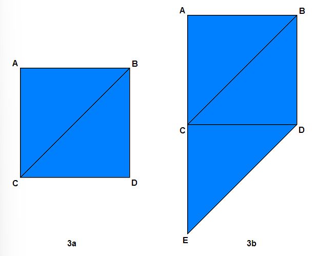
Figure 3a contains a square made up of two triangles; figure 3b contains a pentagonal shape made up of three triangles.
그림 3a에는 두 개의 삼각형으로 이루어진 사각형이 있고, 그림 3b에는 세 개의 삼각형으로 이루어진 오각형 모양이 있다.
We can make the vertex buffer smaller if we can tell the GPU that when rendering the second triangle, instead of fetching all three vertices from the vertex buffer, use 2 of the vertices from the previous triangle and fetch only 1 vertex from the vertex buffer. As it turns out, this is supported by Direct3D, and the topology is called triangle strip.
두 번째 삼각형을 렌더링할 때 GPU가 정점 버퍼에서 세 정점을 모두 가져오는 대신, 이전 삼각형의 정점 중 두 개를 사용하고 정점 버퍼에서 하나의 정점만 가져오도록 지정하면 정점 버퍼 크기를 줄일 수 있다. Direct3D는 이러한 방식을 지원하며, 이를 삼각형 스트립(triangle strip) 토폴로지라고 한다.
When rendering a triangle strip, the very first triangle is defined by the first three vertices in the vertex buffer. The next triangle is defined by the last two vertices of the previous triangle plus the next vertex in the vertex buffer. Taking the square in figure 3a as an example, using triangle strip, the vertex buffer would look like:
삼각형 스트립을 렌더링할 때, 첫 번째 삼각형은 정점 버퍼의 처음 세 정점으로 정의된다. 다음 삼각형은 이전 삼각형의 마지막 두 정점에 정점 버퍼의 다음 정점을 더하여 정의된다. 그림 3a의 사각형을 예로 들면, 삼각형 스트립을 사용하면 정점 버퍼는 다음과 같이 구성된다:
A B C D
The first three vertices, A B C, define the first triangle. The second triangle is defined by B and C, the last two vertices of the first triangle, plus D. Thus, by using the triangle strip topology, the vertex buffer size has gone from 6 vertices to 4 vertices.
처음 세 정점인 A, B, C는 첫 번째 삼각형을 정의한다. 두 번째 삼각형은 첫 번째 삼각형의 마지막 두 정점인 B와 C에 정점 D를 더하여 정의된다. 따라서 삼각형 스트립 토폴로지를 사용하면 정점 버퍼 크기가 6개 정점에서 4개 정점으로 줄어든다.
Similarly, for three triangles such as those in figure 3b, using triangle list would require a vertex buffer such as:
마찬가지로 그림 3b와 같이 세 개의 삼각형의 경우, 삼각형 목록을 사용하면 다음과 같은 정점 버퍼가 필요하다:
A B C C B D C D E
Using triangle strip, the size of the vertex buffer is dramatically reduced:
삼각형 스트립을 사용하면 정점 버퍼의 크기가 극적으로 감소한다:
A B C D E
You may have noticed that in the triangle strip example, the second triangle is defined as B C D. These three vertices do not form a clockwise order. This is a natural phenomenon from using triangle strips. To overcome this, the GPU automatically swaps the order of the two vertices coming from the previous triangle. It only does this for the second triangle, fourth triangle, sixth triangle, eighth triangle, and so on. This ensures that every triangle is defined by vertices in the correct winding order (clockwise, in this case).
삼각형 스트립 예시에서 두 번째 삼각형이 B C D로 정의된다는 것을 눈치챘을 수도 있다. 이 세 정점은 시계 방향 순서를 이루지 않는다. 이는 삼각형 스트립 사용의 자연스러운 현상이다. 이를 극복하기 위해 GPU는 이전 삼각형에서 오는 두 정점의 순서를 자동으로 바꾼다. 이는 두 번째, 네 번째, 여섯 번째, 여덟 번째 삼각형 등 짝수 번째 삼각형에 대해서만 수행된다. 이를 통해 모든 삼각형이 올바른 와인딩 순서(이 경우 시계 방향)로 정점에 의해 정의되도록 보장한다.
Besides triangle list and triangle strip, Direct3D 11 supports many other types of primitive topology. We will not discuss them in this tutorial.
삼각형 목록과 삼각형 스트립 외에도 Direct3D 11은 다른 많은 종류의 프리미티브 토폴로지를 지원한다. 이 튜토리얼에서는 이들을 다루지 않을 것이다.
In our code, we have one triangle, so it doesn’t really matter what we specify. However, we must specify something, so we chose a triangle list.
우리 코드에는 하나의 삼각형만 있으므로 어떤 토폴로지를 지정하든 큰 차이는 없다. 하지만 무언가는 지정해야 하므로 우리는 삼각형 목록을 선택했다.
// Set primitive topology
g_pImmediateContext->IASetPrimitiveTopology( D3D11_PRIMITIVE_TOPOLOGY_TRIANGLELIST );
Rendering the Triangle
The final item missing is the code that does the actual rendering of the triangle. We have created two shaders to for rendering, the vertex shader and pixel shader. The vertex shader is responsible for transforming the individual vertices of the triangles to their correct locations. And the pixel shader is responsible for calculating the final output color for each pixel of the triangle. This is covered in more detail in the next tutorial.
이제 마지막 남은 항목은 삼각형을 실제로 렌더링하는 코드이다. 우리는 렌더링을 위해 정점 셰이더와 픽셀 셰이더 두 가지 셰이더를 만들었다. 정점 셰이더는 삼각형의 개별 정점을 올바른 위치로 변환하는 역할을 담당한다. 픽셀 셰이더는 삼각형의 각 픽셀에 대한 최종 출력 색상을 계산하는 역할을 한다. 이 내용은 다음 튜토리얼에서 더 자세히 다룬다.
To use these shaders we must call ID3D11DeviceContext::VSSetShader() and ID3D11DeviceContext::PSSetShader() respectively. The last thing that we do is call ID3D11DeviceContext::Draw(), which commands the GPU to render using the current vertex buffer, vertex layout, and primitive topology.
이 셰이더들을 사용하려면 각각 ID3D11DeviceContext::VSSetShader()와 ID3D11DeviceContext::PSSetShader()를 호출해야 한다. 마지막으로 할 일은 ID3D11DeviceContext::Draw()를 호출하는 것이다. 이 호출은 현재 정점 버퍼, 정점 레이아웃, 그리고 프리미티브 토폴로지를 사용하여 렌더링하도록 GPU에 명령한다.
The first parameter to Draw() is the number of vertices to send to the GPU, and the second parameter is the index of the first vertex to begin sending. Because we are rendering one triangle and we are rendering from the beginning of the vertex buffer, we use 3 and 0 for the two parameters, respectively. The entire triangle-rendering code looks like the following:
Draw()의 첫 번째 매개변수는 GPU로 보낼 정점의 수이고, 두 번째 매개변수는 보내기 시작할 첫 번째 정점의 인덱스이다. 우리는 하나의 삼각형을 렌더링하고 정점 버퍼의 처음부터 렌더링하므로, 두 매개변수에 각각 3과 0을 사용한다. 전체 삼각형 렌더링 코드는 다음과 같다:
// Render a triangle
g_pImmediateContext->VSSetShader( g_pVertexShader, NULL, 0 );
g_pImmediateContext->PSSetShader( g_pPixelShader, NULL, 0 );
g_pImmediateContext->Draw( 3, 0 );