The Direct3D 11 programmable pipeline is designed for generating graphics for realtime gaming applications.
Direct3D 11의 프로그래밍 가능한 파이프라인은 실시간 게임 실행프로그램을 위한 그래픽을 생성하기 위해 설계되었다.
This section describes the Direct3D 11 programmable pipeline.
이 단락은 Direct3D 11의 프로그래밍 가능한 파이프라인을 서술한다.
The following diagram shows the data flow from input to output through each of the programmable stages.
다음의 다이아그램은 각 프로그래밍 가능한 단계의 입력과 출력을 넘나들며 데이터가 흐르는 것을 보여준다.
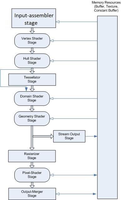
The graphics pipeline for Microsoft Direct3D 11 supports the same stages as the Direct3D 10 graphics pipeline, with additional stages to support advanced features.
마이크로소프트 Direct3D의 그래픽스 파이프라인은 Direct3D 10의 그래픽스 파이프라인과 동일한 단계들을 제공하며, 몇몇 발전된 특성들을 제공하기 위한 추가적인 단계들이 있다.
You can use the Direct3D 11API to configure all of the stages.
당신은 Direct3D 11 API를 사용하여 모든 단계들을 구성할 수 있다.
Stages that feature common shader cores (the rounded rectangular blocks) are programmable by using the HLSL programming language.
공통 셰이더 코어(둥근 직사각형 블록)가 있는 스테이지는 HLSL 언어를 사용하여 프로그래밍할 수 있다.
As you will see, this makes the pipeline extremely flexible and adaptable.
당신이 앞으로 보게 될 것처럼, 이러한 특성은 파이프라인을 매우 유연하고 적응성 있게 만든다.
Input-Assembler Stage
The Direct3D 10 and higher API separates functional areas of the pipeline into stages; the first stage in the pipeline is the input-assembler (IA) stage.
Direct3D 10과 그보다 높은 버전의 API는 pipeline의 기능적인 영역들을 단계(stage)들로 분할한다; 파이프라인의 첫번째 단계는 input-assembler (IA) 단계이다.
The purpose of the input-assembler stage is to read primitive data (points, lines and/or triangles) from user-filled buffers and assemble the data into primitives that will be used by the other pipeline stages.
input-assembler 단계의 목적은 프리미티브 정보(점, 선, 그리고 삼각형)를 사용자 정의 버퍼로부터 읽은 후 데이터를 프리미티브로 조합하는 것이다. 그리고 이러한 프리미티브들은 다른 파이프라인 단계들에 의해 사용되게 된다.
The IA stage can assemble vertices into several different primitive types (such as line lists, triangle strips, or primitives with adjacency).
IA 단계는 정점들을 여러 개의 다른 프리미티브 타입들로 조합할 수 있다 (선 목록, 삼각형 스트립 또는 인접성이 있는 기본 요소 등등)
New primitive types (such as a line list with adjacency or a triangle list with adjacency) have been added to support the geometry shader.
새로운 프리미티브 타입(예: 인접성이 있는 선 목록 또는 인접성이 있는 삼각형 목록)들은 기하학 셰이더를 지원하기 위해서 추가되었다.
Adjacency information is visible to an application only in a geometry shader.
인접 정보는 오로지 기하학 셰이더에서만 볼 수 있다.
If a geometry shader were invoked with a triangle including adjacency, for instance, the input data would contain 3 vertices for each triangle and 3 vertices for adjacency data per triangle.
만약 기하학 셰이더가 인접성을 포함하여 삼각형을 호출한다면, 예를 들어, 입력 데이터는 삼각형의 세 점의 정보를 나타내는 세 개의 정점과 그 점에 대응되는 인접성 정보를 나타내는 세 개의 정점을 가진다.
When the input-assembler stage is requested to output adjacency data, the input data must include adjacency data.
input-assenbler 단계가 인접성 정보를 출력하도록 요청받았을 때, 입력 정보는 반드시 인접성 정보를 포함해야 한다.
This may require providing a dummy vertex (forming a degenerate triangle), or perhaps by flagging in one of the vertex attributes whether the vertex exists or not.
이를 위해서는 더미 정점(퇴화된 삼각형을 형성)를 제공하거나 버텍스의 존재 여부에 관계없이 정점 속성 중 하나에 플래그를 지정해야 할 수도 있다.
This would also need to be detected and handled by a geometry shader, although culling of degenerate geometry will happen in the rasterizer stage.
비록 퇴화 기하 도형이 래스터라이저 단계에서 걸러진다 하더라도 ,이는 또한 기하학 셰이더에 의해 감지되고 조작되어야 한다.
While assembling primitives, a secondary purpose of the IA is to attach system-generated values to help make shaders more efficient.
프리미티브를 조합하는 것에 더불어, IA의 두 번째 목적은 셰이더를 더 효과적으로 만들기 위해 시스템에 의해 생성된 값을 부착하는 것이다.
System-generated values are text strings that are also called semantics.
시스템에 의해 생성된 값은 의미론(semantics)이라고도 불리는 문자열이다.
All three shader stages are constructed from a common shader core, and the shader core uses system-generated values (such as a primitive id, an instance id, or a vertex id) so that a shader stage can reduce processing to only those primitives, instances, or vertices that have not already been processed.
세 셰이더 스테이지는 모두 공통 셰이더 코어로 구성되며, 셰이더 코어는 시스템 생성 값(예: 프리미티브 ID, 인스턴스 ID 또는 버텍스 ID)을 사용하여 셰이더 단계에서 아직 처리되지 않은 프리미티브, 인스턴스 또는 버텍스만 처리하도록 축소할 수 있다.
As shown in the pipeline-block diagram, once the IA stage reads data from memory (assembles the data into primitives and attaches system-generated values), the data is output to the vertex shader stage.
파이프라인 블록 다이어그램에서 보여지듯이, 한번 IA 단계가 메모리로부터 값을 읽으면 (그리고 데이터를 프리미티브로 조립하고, 시스템 생성값을 부착하면), 출력 데이터는 vertex shader stage로 넘어간다.
Getting Started with the Input-Assembler Stage
There are a few steps necessary to initialize the input-assembler (IA) stage.
IA 단계를 초기화하게 위해 필수적인 몇몇 과정들이 있다.
For example, you need to create buffer resources with the vertex data that the pipeline needs, tell the IA stage where the buffers are and what type of data they contain, and specify the type of primitives to assemble from the data.
예를 들어 파이프라인이 필요로 하는, 정점 정보를 가지고 있는 버퍼 리소스를 생성해야 하며, IA 단계에게 버퍼가 어디에 있고 버퍼가 무슨 자료형을 포함하는지를 알려줘야 하며, 데이터로부터 어떤 프리미티브를 조합할지 알려줘야 한다.
The basic steps involved in setting up the IA stage, shown in the following table, are covered in this topic.
이 주제에서는 다음 표에 나와 있는 IA 단계 설정과 관련된 기본 단계를 다룬다.
Create Input Buffers
There are two types of input buffers: vertex buffers and index buffers.
두 종류의 입력 버퍼가 있다: 정점 버퍼와 인덱스 버퍼이다.
Vertex buffers supply vertex data to the IA stage.
정점 버퍼는 정점의 정보를 IA 단계에 공급한다.
Index buffers are optional; they provide indices to vertices from the vertex buffer.
인덱스 버퍼는 선택의 영역이다; 이 버퍼는 정점 버퍼의 정점에 인덱스를 부여한다.
You may create one or more vertex buffers and, optionally, an index buffer.
당신은 하나 혹은 그 이상의 정점 버퍼를 만들게 될 것이며, 선택적으로, 인덱스 버퍼도 만들 수 있다.
After you create the buffer resources, you need to create an input-layout object to describe the data layout to the IA stage, and then you need to bind the buffer resources to the IA stage.
버퍼 리소스를 만든 후에, IA 단계에 데이터 레이아웃을 알려주기 위한 입력 레이아웃 객체를 만들어야 하며, 그런 후에 버퍼 리소스를 IA 단계에 바인딩해야 한다.
Creating and binding buffers is not necessary if your shaders don’t use buffers.
당신의 셰이더가 버퍼를 사용하지 않는다면 버퍼를 생성하고 바인딩할 필요는 없다.
For an example of a simple vertex and pixel shader that draws a single triangle, see Using the Input-Assembler Stage without Buffers.
단순한 정점 셰이더와 픽셀 셰이더로 단일 삼각형을 그리는 예제가 필요하다면 ‘버퍼 없이 IA 단계 사용하기’를 보도록 하자.
For help with creating a vertex buffer, see How to: Create a vertex buffer.
정점 버퍼를 생성하기를 원한다면, ‘정점 버퍼 생성하는 법’을 참고하도록 하자.
For help with creating an index buffer, see How to: Create an index buffer.
인덱스 버퍼 만드는 법에 대해서 도움이 필요하다면, ‘인덱스 버퍼 만드는 법’을 참고하도록 하자.
Create the Input-Layout Object
The input-layout object encapsulates the input state of the IA stage.
입력 레이아웃 객체는 IA 단계의 입력 상태를 캡슐화한다.
This includes a description of the input data that is bound to the IA stage.
이것은 IA 단계에 종속된 입력 데이터에 대한 설명을 포함한다.
The data is streamed into the IA stage from memory, from one or more vertex buffers.
데이터는 메모리에서, 하나 이상의 정점 버퍼에서 IA 단계로 흘러들어간다.
The description identifies the input data that is bound from one or more vertex buffers and gives the runtime the ability to check the input data types against the shader input parameter types.
입력 레이아웃 객체의 설명은 하나 이상의 버텍스 버퍼에서 바인딩된 입력 데이터를 식별하고 런타임이 셰이더 입력 파라미터 유형과 비교하여 입력 데이터 유형을 확인할 수 있는 기능을 제공한다.
This type checking not only verifies that the types are compatible, but also that each of the elements that the shader requires is available in the buffer resources.
타입 확인 절차는 타입이 호환되는지 검증하는데 그치지 않고, 셰이더가 요구하는 모든 원소가 버퍼 리소스에서 사용가능한지도 확인한다.
An input-layout object is created from an array of input-element descriptions and a pointer to the compiled shader (see ID3D11Device::CreateInputLayout). The array contains one or more input elements; each input element describes a single vertex-data element from a single vertex buffer. The entire set of input-element descriptions describes all of the vertex-data elements from all of the vertex buffers that will be bound to the IA stage.
The following layout description describes a single vertex buffer that contains three vertex-data elements:
Copy
D3D11_INPUT_ELEMENT_DESC layout[] =
{
    { L"POSITION", 0, DXGI_FORMAT_R32G32B32_FLOAT, 0, 0,
          D3D11_INPUT_PER_VERTEX_DATA, 0 },
    { L"TEXCOORD", 0, DXGI_FORMAT_R32G32_FLOAT, 0, 12,
          D3D11_INPUT_PER_VERTEX_DATA, 0 },
    { L"NORMAL", 0, DXGI_FORMAT_R32G32B32_FLOAT, 0, 20,
          D3D11_INPUT_PER_VERTEX_DATA, 0 },
};
An input-element description describes each element contained by a single vertex in a vertex buffer, including size, type, location, and purpose. Each row identifies the type of data by using the semantic, the semantic index, and the data format. A semantic is a text string that identifies how the data will be used. In this example, the first row identifies 3-component position data (xyz, for example); the second row identifies 2-component texture data (UV, for example); and the third row identifies normal data.
In this example of an input-element description, the semantic index (which is the second parameter) is set to zero for all three rows. The semantic index helps distinguish between two rows that use the same semantics. Since there are no similar semantics in this example, the semantic index can be set to its default value, zero.
The third parameter is the format. The format (see DXGI_FORMAT) specifies the number of components per element, and the data type, which defines the size of the data for each element. The format can be fully typed at the time of resource creation, or you may create a resource by using a DXGI_FORMAT, which identifies the number of components in an element, but leaves the data type undefined.