Summary
In the previous tutorial, we introduced lighting to our project.
이전 튜토리얼에서 프로젝트에 조명 효과를 추가했다.
Now we will build on that by adding textures to our cube.
이제 큐브에 텍스처를 추가하여 프로젝트를 빌드해 볼 것이다.
Also, we will introduce the concept of constant buffers, and explain how you can use buffers to speed up processing by minimizing bandwidth usage.
또한 상수 버퍼의 개념을 소개하고 버퍼를 사용하여 대역폭 사용량을 최소화하여 처리 속도를 높일 수 있는 방법을 설명한다.
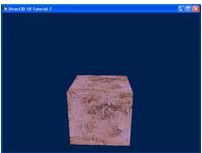
The purpose of this tutorial is to modify the center cube to have a texture mapped onto it.
이번 튜토리얼의 목적은 중앙의 큐브에 텍스처를 매핑하도록 수정하는 것이다.
Source
(SDK root)\Samples\C++\Direct3D11\Tutorials\Tutorial07
Texture Mapping
Texture mapping refers to the projection of a 2D image onto 3D geometry.
텍스처 매핑은 2D 이미지를 3D 기하 세계에 투영하는 것을 말한다.
We can think of it as wrapping a present, by placing decorative paper over an otherwise bland box.
단조로운 상자에 장식 종이를 덮어 선물을 포장하는 것과 같다.
To do this, we have to specify how the points on the surface of the geometry correspond with the 2D image.
이렇게 하려면 기하도형 표면의 점이 2D 이미지와 어떻게 대응하는지 지정해야 한다.
The trick is to properly align the coordinates of the model with the texture.
방법은 모델의 좌표를 텍스처로 적절히 정렬하는 것이다.
For complex models, it is difficult to determine the coordinates for the textures by hand.
복잡한 모델의 경우, 텍스처를 위한 좌표를 직접 계산하는 것은 어렵다.
Thus, 3D modeling packages generally will export models with corresponding texture coordinates.
그러므로, 3차원 모델링 패키지는 일반적으로 대응되는 텍스처 좌표를 동반하여 모델을 제공한다.
Since our example is a cube, it is easy to determine the coordinates needed to match the texture.
우리의 예시가 큐브이기 때문에, 좌표를 텍스처와 맞물리기가 쉽다.
Texture coordinates are defined at the vertices, and are then interpolated for individual pixels on a surface.
텍스처 좌표는 정점에 정의되어 있으며, 표면의 개개의 픽셀에 대해 보간된다.
Creating a Shader Resource from the Texture and Sampler State
The texture is a 2D image that is retrieved from file and used to create a shader-resource view, so that it can be read from a shader.
텍스처는 파일로부터 읽어들이는 2차원 이미지이다. 텍스처는 shader-resource view를 만들기 위해 사용되며, 따라서 셰이더에 의해 읽힐 수 있다.
hr = D3DX11CreateShaderResourceViewFromFile( g_pd3dDevice, L"seafloor.dds", NULL, NULL, &g_pTextureRV, NULL );
We also need to create a sampler state that controls how the shader handles filtering, MIPs, and addressing.
또한 셰이더가 필터링, MIP 및 어드레싱을 처리하는 방법을 제어하는 샘플러 상태를 만들어야 한다.
For this tutorial we will enable simple sampler state that enables linear filtering and wrap addressing.
이번 튜토리얼에서 우리는 간단한 샘플러 상태를 만들어 볼 것이다. 샘플러 상태는 선형 필터링과 주소 래핑을 가능하게 한다.
To create the sampler state, we will use ID3D11Device::CreateSamplerState().
샘플러 상태를 생성하기 위해서, **ID3D11Device::CreateSamplerState()**를 사용한다.
// Create the sample state
D3D11_SAMPLER_DESC sampDesc;
ZeroMemory( &sampDesc, sizeof(sampDesc) );
sampDesc.Filter = D3D11_FILTER_MIN_MAG_MIP_LINEAR;
sampDesc.AddressU = D3D11_TEXTURE_ADDRESS_WRAP;
sampDesc.AddressV = D3D11_TEXTURE_ADDRESS_WRAP;
sampDesc.AddressW = D3D11_TEXTURE_ADDRESS_WRAP;
sampDesc.ComparisonFunc = D3D11_COMPARISON_NEVER;
sampDesc.MinLOD = 0;
sampDesc.MaxLOD = D3D11_FLOAT32_MAX;
hr = g_pd3dDevice->CreateSamplerState( &sampDesc, &g_pSamplerLinear );
Defining the Coordinates
Before we can map the image onto our cube, we must first define the texture coordinates on each of the vertices of the cube.
이미지를 큐브에 매핑하기 위해선, 먼저 큐브의 각 정점의 텍스처 좌표들을 정의해야 한다.
Since images can be of any size, the coordinate system used has been normalized to [0, 1].
이미지는 어떠한 크기도 될 수 있기 때문에, 좌표는 [0, 1] 범위로 정규화된다.
The top left corner of the texture corresponds to (0,0) and the bottom right corner maps to (1,1).
텍스처의 좌측 상단은 (0, 0) 좌표로 대응되며 우측 하단은 (1, 1) 좌표로 대응된다.
In this example, we’re having the whole texture spread across each side of the cube.
이번 예제에서, 전체 텍스처를 큐브의 각 면에 펼칠 것이다.
This simplifies the definition of the coordinates, without confusion.
이것은 왜곡 없이 좌표 정의를 단순화시킨다.
However, it is entirely possible to specify the texture to stretch across all six faces, although it’s more difficult to define the points, and it will appear stretched and distorted.
그러나 텍스처가 여섯 면 모두에 걸쳐 늘어나도록 지정하는 것은 전적으로 가능하지만, 점을 정의하기가 더 어렵고 늘어지고 왜곡된 것처럼 보일 수 있다.
First, we updated the structure used to define our vertices to include the texture coordinates.
먼저 정점을 정의하기 위한 구조체를 텍스처 좌표를 포함하도록 수정한다.
struct SimpleVertex
{
	XMFLOAT3 Pos;
	XMFLOAT2 Tex;
};
Next, we updated the input layout to the shaders to also include these coordinates.
그 다음 셰이더에 전달하는 입력 레이아웃도 텍스처 좌표들을 포함하도록 수정한다.
// Define the input layout
D3D11_INPUT_ELEMENT_DESC layout[] =
{
    { "POSITION", 0, DXGI_FORMAT_R32G32B32_FLOAT, 0, 0, D3D11_INPUT_PER_VERTEX_DATA, 0 },
    { "TEXCOORD", 0, DXGI_FORMAT_R32G32_FLOAT, 0, 12, D3D11_INPUT_PER_VERTEX_DATA, 0 },
};
Since the input layout changed, the corresponding vertex shader input must also be modified to match the addition.
입력 레이아웃이 변경되었기 때문에, 대응되는 정점 셰이더의 입력도 추가사항이 반영되도록 수정해야 한다.
struct VS_INPUT
{
    float4 Pos : POSITION;
    float2 Tex : TEXCOORD;
};
Finally, we are ready to include texture coordinates in our vertices we defined back in Tutorial 4.
마침내, 튜토리얼 4에서 정의했던 정점에 텍스처 좌표를 추가할 준비가 되었다.
Note the second parameter input is a D3DXVECTOR2 containing the texture coordinates.
두번째 파라미터 D3DXVECTOR2는 텍스처 좌표를 포함한다는 사실을 기억하자.
Each vertex on the cube will correspond to a corner of the texture.
큐브의 각 정점은 텍스처의 꼭지점에 대응한다.
This creates a simple mapping where each vertex gets (0,0) (0,1) (1,0) or (1,1) as the coordinate.
이렇게 하면 각 정점이 (0,0) (0,1) (1,0) 또는 (1,1)을 좌표로 받는 간단한 매핑이 생성된다.
// Create vertex buffer
SimpleVertex vertices[] =
{
    { XMFLOAT3( -1.0f, 1.0f, -1.0f ), XMFLOAT2( 0.0f, 0.0f ) },
    { XMFLOAT3( 1.0f, 1.0f, -1.0f ), XMFLOAT2( 1.0f, 0.0f ) },
    { XMFLOAT3( 1.0f, 1.0f, 1.0f ), XMFLOAT2( 1.0f, 1.0f ) },
    { XMFLOAT3( -1.0f, 1.0f, 1.0f ), XMFLOAT2( 0.0f, 1.0f ) },

    { XMFLOAT3( -1.0f, -1.0f, -1.0f ), XMFLOAT2( 0.0f, 0.0f ) },
    { XMFLOAT3( 1.0f, -1.0f, -1.0f ), XMFLOAT2( 1.0f, 0.0f ) },
    { XMFLOAT3( 1.0f, -1.0f, 1.0f ), XMFLOAT2( 1.0f, 1.0f ) },
    { XMFLOAT3( -1.0f, -1.0f, 1.0f ), XMFLOAT2( 0.0f, 1.0f ) },

    { XMFLOAT3( -1.0f, -1.0f, 1.0f ), XMFLOAT2( 0.0f, 0.0f ) },
    { XMFLOAT3( -1.0f, -1.0f, -1.0f ), XMFLOAT2( 1.0f, 0.0f ) },
    { XMFLOAT3( -1.0f, 1.0f, -1.0f ), XMFLOAT2( 1.0f, 1.0f ) },
    { XMFLOAT3( -1.0f, 1.0f, 1.0f ), XMFLOAT2( 0.0f, 1.0f ) },

    { XMFLOAT3( 1.0f, -1.0f, 1.0f ), XMFLOAT2( 0.0f, 0.0f ) },
    { XMFLOAT3( 1.0f, -1.0f, -1.0f ), XMFLOAT2( 1.0f, 0.0f ) },
    { XMFLOAT3( 1.0f, 1.0f, -1.0f ), XMFLOAT2( 1.0f, 1.0f ) },
    { XMFLOAT3( 1.0f, 1.0f, 1.0f ), XMFLOAT2( 0.0f, 1.0f ) },

    { XMFLOAT3( -1.0f, -1.0f, -1.0f ), XMFLOAT2( 0.0f, 0.0f ) },
    { XMFLOAT3( 1.0f, -1.0f, -1.0f ), XMFLOAT2( 1.0f, 0.0f ) },
    { XMFLOAT3( 1.0f, 1.0f, -1.0f ), XMFLOAT2( 1.0f, 1.0f ) },
    { XMFLOAT3( -1.0f, 1.0f, -1.0f ), XMFLOAT2( 0.0f, 1.0f ) },

    { XMFLOAT3( -1.0f, -1.0f, 1.0f ), XMFLOAT2( 0.0f, 0.0f ) },
    { XMFLOAT3( 1.0f, -1.0f, 1.0f ), XMFLOAT2( 1.0f, 0.0f ) },
    { XMFLOAT3( 1.0f, 1.0f, 1.0f ), XMFLOAT2( 1.0f, 1.0f ) },
    { XMFLOAT3( -1.0f, 1.0f, 1.0f ), XMFLOAT2( 0.0f, 1.0f ) },
};
When we sample the texture, we will need to modulate it with a material color for the geometry underneath.
우리가 텍스처를 샘플링할 때, 텍스처를 그 아래 지오메트리의 머티리얼 색상으로 변조해야 한다.
Bind Texture as Shader Resource
A texture and sampler state are objects like the constant buffers that we have seen in previous tutorials.
텍스처와 샘플러 상태는 이전 튜토리얼에서 살펴본 상수 버퍼와 같은 객체이다.
Before they can be used by the shader, they need to be set with the ID3D11DeviceContext::PSSetSamplers() and ID3D11DeviceContext::PSSetShaderResources() APIs.
셰이더에서 사용하려면 ID3D11DeviceContext::PSSetSamplers() 및 ID3D11DeviceContext::PSSetShaderResources() API를 사용하여 설정해야 한다.
g_pImmediateContext->PSSetShaderResources( 0, 1, &g_pTextureRV );
g_pImmediateContext->PSSetSamplers( 0, 1, &g_pSamplerLinear );
There we go, now we’re ready to use the texture within the shader.
이제 셰이더 내에서 텍스처를 사용할 준비가 되었다.
Applying the Texture
To map the texture on top of the geometry, we will be calling a texture lookup function within the pixel shader. The function Sample will perform a texture lookup of a 2D texture, and then return the sampled color. The pixel shader shown below calls this function and multiplies it by the underlying mesh color (or material color), and then outputs the final color.
지오메트리 위에 텍스처를 매핑하기 위해 픽셀 셰이더 내에서 텍스처 룩업 함수를 호출할 것입니다. Sample 함수는 2D 텍스처의 텍스처 룩업을 수행한 다음 샘플링된 색상을 반환합니다. 아래 표시된 픽셀 셰이더는 이 함수를 호출하여 기본 메쉬 색상(또는 머티리얼 색상)을 곱한 다음 최종 색상을 출력합니다.
-
txDiffuse is the object storing our texture that we passed in from the code above, when we bound the resource view g_pTextureRV to it.
-
samLinear will be described below; it is the sampler specifications for the texture lookup.
-
input.Tex is the coordinates of the texture that we have specified in the source.
-
txDiffuse는 위 코드에서 리소스 뷰 g_pTextureRV를 바인딩할 때 전달한 텍스처를 저장하는 객체입니다.
-
아래에서 설명할 samLinear는 텍스처 룩업을 위한 샘플러 사양입니다.
-
input.Tex는 소스에서 지정한 텍스처의 좌표입니다.
// Pixel Shader
float4 PS( PS_INPUT input) : SV_Target
{
    return txDiffuse.Sample( samLinear, input.Tex ) * vMeshColor;
}
Another thing we must remember to do is to pass the texture coordinates through the vertex shader. If we don’t, the data is lost when it gets to the pixel shader. Here, we just copy the input’s coordinates to the output, and let the hardware handle the rest.
또 한 가지 기억해야 할 것은 텍스처 좌표를 버텍스 셰이더로 전달하는 것입니다. 그렇지 않으면 데이터가 픽셀 셰이더에 도달할 때 데이터가 손실됩니다. 여기서는 입력의 좌표만 출력으로 복사하고 나머지는 하드웨어가 처리하도록 합니다.
// Vertex Shader
PS_INPUT VS( VS_INPUT input )
{
    PS_INPUT output = (PS_INPUT)0;
    output.Pos = mul( input.Pos, World );
    output.Pos = mul( output.Pos, View );
    output.Pos = mul( output.Pos, Projection );
    output.Tex = input.Tex;

    return output;
}
Constant Buffers
In Direct3D 11, an application can use a constant buffer to set shader constants (shader variables). Constant buffers are declared using a syntax similar to C-style structs. Constant buffers reduce the bandwidth required to update shader constants by allowing shader constants to be grouped together and committed at the same time, rather than making individual calls to commit each constant separately.
In the previous tutorials, we used a single constant buffer to hold all of the shader constants we need. But the best way to efficiently use constant buffers is to organize shader variables into constant buffers based on their frequency of update. This allows an application to minimize the bandwidth required for updating shader constants. As an example, this tutorial groups constants into three structures: one for variables that change every frame, one for variables that change only when a window size is changed, and one for variables that are set once and then do not change.
The following constant buffers are defined in this tutorial’s .fx file.
Direct3D 11에서 애플리케이션은 상수 버퍼를 사용하여 셰이더 상수(셰이더 변수)를 설정할 수 있습니다. 상수 버퍼는 C 스타일 구조체와 유사한 구문을 사용하여 선언됩니다. 상수 버퍼는 각 상수를 개별적으로 커밋하기 위해 개별적으로 호출하는 대신 셰이더 상수를 그룹화하여 동시에 커밋할 수 있도록 하여 셰이더 상수 업데이트에 필요한 대역폭을 줄여줍니다.
이전 튜토리얼에서는 하나의 상수 버퍼에 필요한 모든 셰이더 상수를 저장하는 방법을 사용했습니다. 하지만 상수 버퍼를 효율적으로 사용하는 가장 좋은 방법은 셰이더 변수를 업데이트 빈도에 따라 상수 버퍼로 구성하는 것입니다. 이렇게 하면 애플리케이션에서 셰이더 상수를 업데이트하는 데 필요한 대역폭을 최소화할 수 있습니다. 예를 들어, 이 튜토리얼에서는 상수를 매 프레임마다 변경되는 변수, 창 크기가 변경될 때만 변경되는 변수, 한 번 설정된 후 변경되지 않는 변수의 세 가지 구조로 그룹화합니다.
이 튜토리얼의 .fx 파일에는 다음과 같은 상수 버퍼가 정의되어 있습니다.
cbuffer cbNeverChanges
{
	matrix View;
};

cbuffer cbChangeOnResize
{
	matrix Projection;
};

cbuffer cbChangesEveryFrame
{
	matrix World;
	float4 vMeshColor;
};
To work with these constant buffers, you need to create a ID3D11Buffer object for each one. Then you can call ID3D11DeviceContext::UpdateSubresource() to update each constant buffer when needed without affecting the other constant buffers.
이러한 상수 버퍼로 작업하려면 각 버퍼에 대해 ID3D11Buffer 오브젝트를 생성해야 합니다. 그런 다음 다른 상수 버퍼에 영향을 주지 않고 필요할 때 **ID3D11DeviceContext::UpdateSubresource()**를 호출하여 각 상수 버퍼를 업데이트할 수 있습니다.
//
// Update variables that change once per frame
//
CBChangesEveryFrame cb;
cb.mWorld = XMMatrixTranspose( g_World );
cb.vMeshColor = g_vMeshColor;
g_pImmediateContext->UpdateSubresource( g_pCBChangesEveryFrame, 0, NULL, &cb, 0, 0 );