Summary
In the previous tutorial, we successfully rendered a triangle in the center of our application window.
이전 튜토리얼에서, 실행프로그램 창의 정중앙에 성공적으로 삼각형을 그렸다.
We haven’t paid much attention to the vertex positions that we have picked in our vertex buffer.
정점 버퍼에 넣었던 정점 좌표에 대해서 그다지 주의를 기울이지 않았었다.
In this tutorial, we will delve into the details of 3D positions and transformation.
이번 튜토리얼에서, 3차원 좌표와 변환의 세부사항에 대해서 자세히 알아볼 것이다.
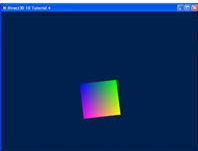
The outcome of this tutorial will be a 3D object rendered to screen.
이번 튜토리얼이 끝나면 스크린에 3차원 물체를 그릴 수 있을 것이다.
Whereas previous tutorials focused on rendering a 2D object onto a 3D world, here we show a 3D object.
이전 튜토리얼에서는 3차원 공간에 2차원 물체를 그리는데 집중했지만, 이번에는 3차원 물체를 띄울 것이다.
Source
(SDK root)\Samples\C++\Direct3D11\Tutorials\Tutorial04
3D Spaces
In the previous tutorial, the vertices of the triangle were placed strategically to perfectly align themselves on the screen.
이전 강의에서 삼각형의 꼭짓점들을 화면에 완벽히 정렬되도록 전략적으로 배치했다.
However, this will not always be the case. Thus, we need a system to denote objects in 3D space and a system to display them.
그러나, 이것이 항상 유효하지는 않다. 따라서, 3D 공간에서 객체들을 나타내는 시스템과 그것들을 표시하는 시스템이 필요하다.
In the real world, objects exist in 3D space.
현실세계에서 물체는 3차원 공간에 존재한다.
This means that to place an object in a particular position in the world, we would need to use a coordinate system and define three coordinates that correspond to the position.
이것은 물체를 세계의 특정 좌표에 배치할 때, 좌표계를 사용할 필요가 있으며 위치에 대응되는 3차원 좌표가 정의되어야 함을 의미한다.
In computer graphics, 3D spaces are most commonly in Cartesian coordinate system.
컴퓨터 그래픽스에서, 3차원 공간은 보통 카르테시안 좌표계이다.
In this coordinate system, three axes, X, Y, and Z, perpendicular to each other, dictate the coordinate that each point in the space has.
이 좌표계에서 서로 직교하는 축 X, Y, Z는 점의 공간에서의 좌표를 지시한다(나타낸다.)
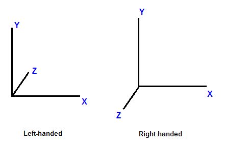
This coordinate system is further divided into left-handed and right-handed systems.
좌표계는 왼손 좌표계와 오른손 좌표계로 나뉜다.
In a left-handed system, when X axis points to the right and Y axis points to up, Z axis points forward.
왼손 좌표계에서 X축은 왼쪽을 가리키며, Y 축은 위쪽, Z 축은 앞쪽을 나타낸다.
In a right-handed system, with the same X and Y axes, Z axis points backward.
오른손 좌표계에서, X, Y 축은 동일하며, Z 축은 뒤쪽을 나타낸다.
Figure 1. Left-handed versus right-handed coordinate systems
보기 1. 왼손 좌표계와 오른손 좌표계
Now that we have talked about the coordinate system, consider 3D spaces.
이제 좌표계에 대해 이야기했으니 3D 공간에 대해 고민해보자.
A point has different coordinates in different spaces.
한 점은 서로 다른 공간에서 다른 좌표를 가진다.
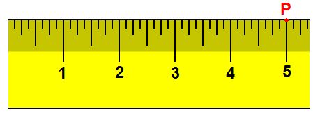
As an example in 1D, suppose we have a ruler and we note the point, P, at the 5-inch mark of the ruler.
1차원 공간을 예로 들면, 자를 가지고 있고 그 위의 5인치 지점에 점 P를 찍는다고 고려하자.
Now, if we move the ruler 1 inch to the right, the same point lies on the 4-inch mark.
이제, 우리가 자를 1인치 우측으로 옮기면, 같은 점은 4인치 지점에 위치하게 된다.
By moving the ruler, the frame of reference has changed.
자를 옮김으로서, 기준 틀이 변경되었다.
Therefore, while the point hasn’t moved, it has a new coordinate.
그러므로, 점이 움직이지 않았음에도, 점은 새로운 좌표를 가지게 되었다.
Figure 2. Spaces illustration in 1D
보기 2. 1차원 공간의 시각화화
In 3D, a space is typically defined by an origin and three unique axes from the origin: X, Y and Z.
3차원에서, 공간은 일반적으로 원점과 원점에서 뻗어나가는 세 개의 고유한 축 X, Y, Z로 정의된다.
There are several spaces commonly used in computer graphics: object space, world space, view space, projection space, and screen space.
컴퓨터 그래픽스에서 일반적으로 사용되는 좌표계들은 다음과 같다: 오브젝트 좌표계, 월드 좌표계, 뷰 좌표계, 투영 좌표계, 스크린 좌표계
Figure 3. A cube defined in object space
보기 3. 오브젝트 공간에 정의된 육면체체
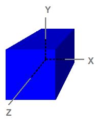
Object Space
Notice that the cube is centered on the origin.
육면체의 중점은 원점이라고 가정한다.
Object space, also called model space, refers to the space used by artists when they create the 3D models.
모델 공간이라고도 불리는 오브젝트 공간은 아티스트들이 3차원 모델을 만들때 사용하는 공간이다.
Usually, artists create models that are centered around the origin so that it is easier to perform transformations such as rotations to the models, as we will see when we discuss transformation.
일반적으로, 아티스트들은 모델의 중앙이 원점에 위치하도록 한다. 왜냐하면 그렇게 하는 것이 모델에 회전과 같은 변환을 부여하기 더 쉽기 때문이다. 변환에 대해 논할 때 이것을 알아볼 것이다.
The eight vertices have the following coordinates:
(6면체를 구성하는) 8개의 정점들은 다음과 같다:
(-1,  1, -1)
( 1,  1, -1)
(-1, -1, -1)
( 1, -1, -1)
(-1,  1,  1)
( 1,  1,  1)
(-1, -1,  1)
( 1, -1,  1)
Because object space is what artists typically use when they design and create models, the models that are stored on disk are also in object space.
오브젝트 공간은 아티스트들이 모델을 디자인하고 생성하는데 사용하기 때문에, 디스크에 저장되어 있는 모델들 또한 오브젝트 공간에 있다.
An application can create a vertex buffer to represent such a model and initialize the buffer with the model data.
실행 프로그램은 그러한 모델을 나타내는 정점 버퍼를 생성할 수 있으며 모델의 데이터를 사용하여 버퍼를 초기화할 수 있다.
Therefore, the vertices in the vertex buffer will usually be in object space as well.
그러므로, 정점 버퍼의 정점들은 일반적으로 오브젝트 공간에 위치한다.
This also means that the vertex shader receives input vertex data in object space.
이는 또한 정점 셰이더가 오브젝트 공간의 정점을 입력으로 받는다는 의미이기도 하다.
World Space
World space is a space shared by every object in the scene.
월드 좌표계는 장면을 구성하는 모든 물체들이 공유하는 좌표계이다.
It is used to define spatial relationship between objects that we wish to render.
월드 좌표계는 우리가 그리고자 하는 물체들간의 공간적인 관계를 정의한다.
To visualize world space, we could imagine that we are standing in the south-western corner of a rectangular room facing north.
월드 좌표계를 시각화하기 위해서, 우리가 직사각형 방의 남서쪽 구석에서 북쪽을 향해 보고 서있다고 가정해보자.
We define the corner that our feet are standing at to be the origin, (0, 0, 0).
그리고 우리가 서있는 구석을 원점 (0, 0, 0) 이라고 생각해보자.
The X axis goes to our right; the Y axis goes up; and the Z axis goes forward, the same direction as we are facing.
x축은 우리의 오른쪽을 향해 뻗으며, Y는 위로, Z는 우리가 보고 있는 방향인 앞으로 뻗는다.
When we do this, every position in the room can be identified with a set of XYZ coordinates.
이렇게 했을 때, 방 안의 모든 물체는 XYZ 좌표의 집합으로 나타낼 수 있다.
For instance, there may be a chair 5 feet in front and 2 feet to the right of us.
예를 들어, 의자가 나를 기준으로 5피트 앞쪽, 그리고 2피트 오른쪽에 있을 수 있다.
There may be a light on the 8-foot-high ceiling directly on top of the chair.
의자 바로 위, 8피트 높이의 천장에 조명이 있을 수 있다.
We can then refer to the position of the chair as (2, 0, 5) and the position of the light as (2, 8, 5).
그렇다면 의자의 위치를 (2, 0, 5), 조명의 위치를 (2, 8, 5)로 나타낼 수 있다.
As we see, world space is so-called because they tell us where objects are in relation to each other in the world.
이렇듯, 월드 공간은 물체들이 세계 안에서 서로 어떻게 위치하는지를 알려주기 때문에 그렇게 불린다.
View Space
View space, sometimes called camera space, is similar to world space in that it is typically used for the entire scene.
이따금 카메라 공간으로 불리는 뷰 공간은 전체 장면을 표현하기 위해 쓰인다는 점에서 월드 공간과 유사하다.
However, in view space, the origin is at the viewer or camera.
하지만 뷰 공간에서 원점은 관찰자 또는 카메라이다.
The view direction (where the viewer is looking) defines the positive Z axis.
관찰자 또는 카메라가 보고 있는 방향이 뷰 공간의 양의 Z축을 정의한다.
An “up” direction defined by the application becomes the positive Y axis as shown below.
애플리케이션에 의해 정의된 “위쪽” 방향은 아래에 보이는 것처럼 양의 Y축이 된다.
Figure 4. The same object in world space (left) and in view space (right)
보기 4. 같은 물체가 월드 공간(왼쪽) 그리고 뷰 공간(오른쪽)에 있는 모습
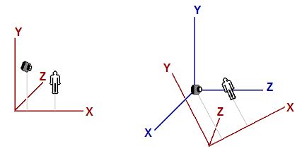
The left image shows a scene that consists of a human-like object and a viewer (camera) looking at the object.
왼쪽 그림은 사람 모양의 물체와 그 물체를 바라보는 관찰자(카메라)로 이루어진다.
The origin and axes that are used by world space are shown in red.
월드 공간의 원점과 축은 빨간색으로 나타냈다.
The right image shows the view space in relation to world space.
오른쪽 그림은 월드 공간에 대응되는 뷰 공간이다.
The view space axes are shown in blue.
뷰 공간의 축들은 파란색으로 나타냈다.
For clearer illustration, the view space does not have the same orientation as the world space in the left image to readers.
더 명확한 그림을 위해, 뷰 공간은 왼쪽 이미지의 월드 공간과 동일한 방향 설정을 가지지 않는다.
Note that in view space, the viewer is looking in the Z direction.
뷰 공간에서는 관찰자가 바라보는 방향이 Z 축이 된다는 사실을 알아두자.
Projection Space
Projection space refers to the space after applying projection transformation from view space.
투영 공간은 뷰 공간에 투영 변환을 실행한 결과이다.
In this space, visible content has X and Y coordinates ranging from -1 to 1, and Z coordinate ranging from 0 to 1.
이 공간에서, 보이는(다른 물체에 가려지지 않은 걸 말하는듯) 물체는 [-1, 1] 범위의 x, y좌표를 가지며, z 좌표의 범위는 [0, 1]이다.
Screen Space
Screen space is often used to refer to locations in the frame buffer.
스크린 공간은 보통 프레임 버퍼 내의 위치를 나타내는 데 사용된다.
Because frame buffer is usually a 2D texture, screen space is a 2D space.
프레임 버퍼는 일반적으로 2D 텍스처이기 때문에, 스크린 공간은 2차원 공간이다.
The top-left corner is the origin with coordinates (0, 0).
좌측 상단의 구석은 원점 (0, 0)이다.
The positive X goes to right and positive Y goes down.
X축 양의 방향은 오른쪽이며 Y축 양의 방향은 아래쪽이다.
For a buffer that is w pixels wide and h pixels high, the most lower-right pixel has the coordinates (w - 1, h - 1).
w 픽셀만큼의 넓이, h 픽셀만큼의 높이를 가지는 버퍼의 최우측-하단 픽셀의 좌표는 (w - 1, h - 1)이다.
Space-to-space Transformation
Transformation is most commonly used to convert vertices from one space to another.
변환은 정점을 하나의 공간에서 다른 공간으로 옮기는 데 보통 사용된다.
In 3D computer graphics, there are logically three such transformations in the pipeline: world, view, and projection transformation.
3D 컴퓨터 그래픽스에서 파이프라인에는 논리적으로 세 가지 변환, 즉 월드 변환, 뷰 변환, 그리고 투영 변환이 있다.
Individual transformation operations such as translation, rotation, and scaling are covered in the next tutorial.
이동, 회전, 스케일링 같은 개개의 변환 연산은 다음 튜토리얼에서 다루도록 한다.
World Transformation
World transformation, as the name suggests, converts vertices from object space to world space.
월드 변환은 그 이름에서 알 수 있듯이, 정점을 오브젝트 공간에서 월드 공간으로 전환하는 것이다.
It usually consists of one or more scaling, rotation, and translation, based on the size, orientation, and position we would like to give to the object.
월드 변환은 보통 하나 혹은 그 이상의 스케일링, 회전, 이동으로 구성되어 있으며 각 동작은 우리가 물체에 부여하고자 하는 크기, 방향, 위치와 연관되어 있다.
Every object in the scene has its own world transformation matrix.
장면의 모든 물체는 각기 고유의 월드 변환 행렬을 가진다.
This is because each object has its own size, orientation, and position.
왜냐하면 각 오브젝트는 고유의 크기, 방향, 위치를 가지기 때문이다.
View Transformation
After vertices are converted to world space, view transformation converts those vertices from world space to view space.
정점들이 월드 공간으로 변환된 후, 뷰 변환이 정점들을 월드 공간에서 뷰 공간으로 이동시킨다.
Recall from earlier discussion that view space is what the world appears from the viewer’s (or camera’s) perspective.
앞서 논의한 바와 같이, 뷰 공간은 관찰자(또는 카메라)의 관점에서 세계가 보이는 공간이다.
In view space, the viewer is located at origin looking out along the positive Z axis.
뷰 공간에서, 관찰자는 원점에 위치해 있으며 양의 z 축 방향을 바라본다.
It is worth noting that although view space is the world from the viewer’s frame of reference, view transformation matrix is applied to vertices, not the viewer.
뷰 공간이 관찰자의 기준 틀에서 본 세계임에도 불구하고, 뷰 변환 행렬은 관찰자가 아니라 꼭짓점들에 적용된다는 점을 주목할 필요가 있다.
Therefore, the view matrix must perform the opposite transformation that we apply to our viewer or camera.
그러므로, 뷰 행렬은 관찰자나 카메라에 수행되는 변환의 반대되는 변환을 수행해야 한다.
For example, if we want to move the camera 5 units towards the -Z direction, we would need to compute a view matrix that translates vertices for 5 units along the +Z direction.
예를 들어, 우리가 카메라를 -Z 방향으로 5만큼 이동시키기를 바라면, 우리는 뷰 행렬이 정점들을 +Z축 방향으로 움직이게끔 계산할 필요가 있다.
Although the camera has moved backward, the vertices, from the camera’s point of view, have moved forward.
비록 카메라가 뒤쪽으로 움직였지만, 카메라의 시점에서 볼 때 정점들은 앞으로 움직인 것이다.
In XNA Math a convenient API call XMMatrixLookAtLH() is often used to compute a view matrix.
XNA Math에서는 뷰 행렬을 계산하기 위해 편리한 API 호출인 **XMMatrixLookAtLH()**가 자주 사용된다.
We would simply need to tell it where the viewer is, where it’s looking at, and the direction representing the viewer’s top, also called the up-vector, to obtain a corresponding view matrix.
단순히 관찰자가 어디에 있는지, 어디를 바라보는지, 그리고 관찰자의 위쪽을 나타내는 방향(업 벡터라고도 불리는)을 알려주기만 하면, 이에 해당하는 뷰 행렬을 얻을 수 있다.
Projection Transformation
Projection transformation converts vertices from 3D spaces such as world and view spaces to projection space.
투영 변환은 정점을 월드 또는 뷰 공간 같은 3차원 공간에서 투영 공간으로 변환한다.
In projection space, X and Y coordinates of a vertex are obtained from the X/Z and Y/Z ratios of this vertex in 3D space.
투영 공간에서, 정점의 X Y 좌표는 3차원 공간의 X/Z 그리고 Y/Z 비율을 통해서 얻는다.
Figure 5. Projection
보기 5. 투영
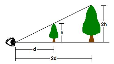
In 3D space, things appear in perspective.
3차원 공간에서, 물체는 원근법으로 나타내어진다.
That is, the closer an object is, the larger it appears.
물체가 가까이 있을수록 커보인단 소리다.
As shown, the tip of a tree that is h units tall at d units away from the viewer’s eye will appear at the same point as the tip of another tree 2h units tall and 2d units away.
보기에서, 관찰자의 눈으로부터 d 만큼 떨어져있는 h 높이의 나무의 꼭대기는 2d만큼 떨어져 있는 2h 높이의 나무의 꼭대기와 동일한 지점에 나타내게 된다.
Therefore, where a vertex appears on a 2D screen is directly related to its X/Z and Y/Z ratios.
그러므로 2차원 스크린의 정점은 X/Z 그리고 Y/Z 비율에 대응된다.
One of the parameters that defines a 3D space is called the field-of-view (FOV).
3D 공간을 정의하는 매개변수 중 하나는 시야(Field-of-View, FOV)이다.
FOV denotes which objects are visible from a particular position, while looking in a particular direction.
FOV는 특정 위치에서 특정 방향을 바라볼 때 어떤 객체들이 보이는지 나타낸다.
Humans have a FOV that is forward-looking (we can’t see what is behind us), and we can’t see objects that are too close or too far away.
인간은 앞을 향한 시야(FOV)를 가지며, 뒤에 있는 것은 볼 수 없고, 너무 가깝거나 너무 멀리 있는 객체도 볼 수 없다.
In computer graphics, the FOV is contained in a view frustum.
컴퓨터 그래픽스에서, FOV는 절두체에 포함된다.
The view frustum is defined by 6 planes in 3D.
절두체는 3차원 공간에서 6개의 평면으로 정의된다.
Two of these planes are parallel to the XY plane.
이 평면 중 2개는 XY 평면과 평행하다.
These are called the near-Z and far-Z planes.
이것들을 근거리 Z면, 원거리 Z면이라 부른다.
The other four planes are defined by the viewer’s horizontal and vertical field of view.
나머지 4개의 평면은 관찰자의 수평 및 수직 시야(Field of View)에 의해 정의된다.
The wider the FOV is, the wider the frustum volume is, and the more objects the viewer sees.
FOV가 넓어질수록, 절두차의 부피가 커지며, 관찰자가 바라보는 물체도 커진다.
The GPU filters out objects that are outside the view frustum so that it does not have to spend time rendering something that will not be displayed.
GPU는 절두체 바깥의 물체를 걸러내므로 그려지지 않을 물체를 렌더링하는데 시간을 허비하지 않는다.
This process is called clipping.
이 절차를 클리핑이라 불린다.
The view frustum is a 4-sided pyramid with its top cut off.
절두체는 윗부분이 잘려나간 사각뿔과 같다.
Clipping against this volume is complicated because to clip against one view frustum plane, the GPU must compare every vertex to the plane’s equation.
절두체에 대하여 클리핑을 시도하는 것으나 복잡하다. 왜냐하면 하나의 절두체 평면에 대해 클리핑하려면 GPU가 모든 꼭짓점을 평면의 방정식과 비교해야 하기 때문이다.
Instead, the GPU generally performs projection transformation first, and then clips against the view frustum volume.
대신, GPU는 일반적으로 먼저 투영 변환을 수행한 다음, 절두체 영역에 대해 클리핑을 수행한다.
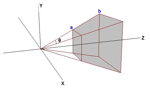
The effect of projection transformation on the view frustum is that the pyramid shaped view frustum becomes a box in projection space.
투영 변환이 절두체에 미치는 영향은, 피라미드 형태의 뷰 절두체가 투영 공간에서 박스 형태로 변환된다는 것이다.
This is because, as mentioned previously, in projection space the X and Y coordinates are based on the X/Z and Y/Z in 3D space.
왜냐하면, 이전에 언급했듯이, 투영 공간에서 X, Y 좌표는 3차원 공간의 X/Z, Y/Z 비에 대응되기 때문이다.
Therefore, point a and point b will have the same X and Y coordinates in projection space, which is why the view frustum becomes a box.
그러므로, 점 a와 점 b는 투영 공간에서 동일한 X, Y 좌표를 가진다. 이것이 절두체가 박스 형태가 되는 이유이다.
Figure 6. View Frustum
보기 6. 절두체
Suppose that the tips of the two trees lie exactly on the top view frustum edge.
두 나무의 꼭대기가 정확히 뷰 절두체 상단 가장자리에 위치한다고 가정하자.
Further suppose that d = 2h.
나아가 라고 가정하자
The Y coordinate along the top edge in projection space will then be 0.5 (because h/d = 0.5).
그러면 절두체의 상단 평면에 걸처 있는 Y좌표는 0.5일 것이다. 왜냐하면 이기 때문이다.
Therefore, any Y values post-projection that are greater than 0.5 will be clipped by the GPU.
따라서, 투영 후 Y 값이 0.5보다 큰 모든 값은 GPU에 의해 클리핑된다.
The problem here is that 0.5 is determined by the vertical field of view chosen by the program, and different FOV values result in different values that the GPU has to clip against.
문제는 0.5가 프로그램에서 선택한 수직 시야(FOV)에 의해 결정되며, 서로 다른 FOV 값들은 GPU가 클리핑해야 하는 값들도 다르게 만든다.
To make the process more convenient, 3D programs generally scale the projected X and Y values of vertices so that the visible X and Y values range from -1 to 1.
과정을 더 간편히 하기 위해, 3차원 프로그램은 일반적으로 정점의 투영된 X, Y 값의 크기를 조정하여 가시 범위 내의 X Y 값이 [-1, 1]에 위치하도록 한다.
In other words, anything with X or Y coordinate that’s outside the [-1 1] range will be clipped out.
다르게 말하면, [-1, 1] 범위 밖의 좌표는 걸러져 나간단 뜻이다.
To make this clipping scheme work, the projection matrix must scale the X and Y coordinates of projected vertices by the inverse of h/d, or d/h.
이 클리핑 방식을 작동시키기 위해, 투영 행렬은 투영된 꼭짓점들의 X와 Y 좌표를 h/d의 역수인 d/h로 스케일해야 한다.
d/h is also the cotangent of half of FOV.
는 FOV의 절반의 코탄젠트 값이다.
With scaling, the top of the view frustum becomes h/d * d/h = 1.
스케일링을 통해 절두체의 상단은 이 된다.
Anything greater than 1 will be clipped by the GPU.
1보다 큰 값은 GPU에 의해 걸러지게 된다.
This is what we want.
이것이 우리가 원하는 것이다.
A similar tweak is generally done for the Z coordinate in projection space as well.
유사한 조정이 일반적으로 투영 공간의 Z 좌표에도 이루어진다.
We would like the near and far Z planes to be at 0 and 1 in projection space, respectively.
우리는 근 Z면과 원 Z면이 각각 투영 공간의 0과 1에 위치하기를 바란다.
When Z = near-Z value in 3D space, Z should be 0 in projection space; when Z = far-Z in 3D space, Z should be 1 in projection space.
3D 공간에서 Z가 근거리 Z값일 때, 투영 공간에서 Z는 0이어야 하며; 3D 공간에서 Z가 원거리 Z값일 때, 투영 공간에서 Z는 1이어야한다.
After this is done, any Z values outside [0 1] will be clipped out by the GPU.
이 과정을 통해 [0, 1] 범위를 넘어가는 Z 값은 GPU에 의해 걸러지게 된다.
In Direct3D 11, the easiest way to obtain a projection matrix is to call the XMMatrixPerspectiveFovLH() method.
Direct3D 11에서 투영 행렬을 얻는 가장 쉬운 방법은 **XMMatrixPerspectiveForLH()**이다.
우리는 단순히 네 개의 매개변수—FOVy, Aspect, Zn, 그리고 Zf—를 제공하고, 위에서 언급한 모든 작업을 수행하는 행렬을 얻는다.
FOVy is the field of view in Y direction.
FOVy는 FOV의 y 방향이다.
Aspect is the aspect ratio, which is ratio of view space width to height.
Aspect는 가로 세로 비율로, 뷰 공간의 너비와 높이의 비를 나타낸다.
From FOVy and Aspect, FOVx can be computed.
FOVy와 Aspect가 있으면 FOVx는 계산할 수 있다.
This aspect ratio is usually obtained from the ratio of the render target width to height.
이 가로 세로 비율은 보통 렌더 타켓의 너비와 높이를 통해 얻는다.
Zn and Zf are the near and far Z values in view space, respectively.
Zn과 Zf는 각각 뷰공간의 근 Z와 원 Z의 값이다.
Using Transformation
In the previous tutorial, we wrote a program that renders a single triangle to screen.
이전 튜토리얼에서, 우리는 삼각형 하나를 화면에 띄우는 프로그램을 작성했다.
When we create the vertex buffer, the vertex positions that we use are directly in projection space so that we don’t have to perform any transformation.
정점 버퍼를 생성할 때, 우리가 어떠한 변환도 수행하지 않았기 때문에 정점의 위치는 바로 투영 공간에서 사용되었다.
Now that we have an understanding of 3D space and transformation, we are going to modify the program so that the vertex buffer is defined in object space, as it should be.
이제 3차원 공간과 변환에 대해 이해하였으므로, 정점 버퍼가 오브젝트 공간을 정의하도록 수정해보자.
Then, we will modify our vertex shader to transform the vertices from object space to projection space.
그런 다음, 정점 셰이더가 정점을 오브젝트 공간에서 투영 공간으로 옮기게 하도록 수정할 것이다.
Modifying the Vertex Buffer
Since we started representing things in three dimensions, we have changed the flat triangle from the previous tutorial to a cube.
우리가 사물을 3차원으로 표현하기 시작했기 때문에, 이전 튜토리얼의 평면 삼각형을 큐브로 변경했다.
This will allow us to demonstrate these concepts much clearer.
이는 배운운 개념들을 훨씬 더 명확하게 시연할 수 있게 해줄 것이다.
SimpleVertex vertices[] =
{
	{ XMFLOAT3( -1.0f,  1.0f, -1.0f ), XMFLOAT4( 0.0f, 0.0f, 1.0f, 1.0f ) },
	{ XMFLOAT3(  1.0f,  1.0f, -1.0f ), XMFLOAT4( 0.0f, 1.0f, 0.0f, 1.0f ) },
	{ XMFLOAT3(  1.0f,  1.0f,  1.0f ), XMFLOAT4( 0.0f, 1.0f, 1.0f, 1.0f ) },
	{ XMFLOAT3( -1.0f,  1.0f,  1.0f ), XMFLOAT4( 1.0f, 0.0f, 0.0f, 1.0f ) },
	{ XMFLOAT3( -1.0f, -1.0f, -1.0f ), XMFLOAT4( 1.0f, 0.0f, 1.0f, 1.0f ) },
	{ XMFLOAT3(  1.0f, -1.0f, -1.0f ), XMFLOAT4( 1.0f, 1.0f, 0.0f, 1.0f ) },
	{ XMFLOAT3(  1.0f, -1.0f,  1.0f ), XMFLOAT4( 1.0f, 1.0f, 1.0f, 1.0f ) },
	{ XMFLOAT3( -1.0f, -1.0f,  1.0f ), XMFLOAT4( 0.0f, 0.0f, 0.0f, 1.0f ) },
};
If you notice, all we did was specify the eight points on the cube, but we didn’t actually describe the individual triangles.
알아차렸을수도 있겠지만, 우리가 한 일은 큐브의 여덟 개 점을 지정한 것뿐이고, 실제로 개별 삼각형들을 정의하지는 않았다.
If we passed this in as-is, the output would not be what we expect.
이 상태 그대로 데이터를 전달하면 출력 결과는 기대한 대로 나오지 않는다.
We will need to specify the triangles that form the cube through these eight points.
큐브를 구성하는 삼각형들을 이 여덟 개의 점들을 통해 명시해주어야 한다.
On a cube, many triangles will be sharing the same vertex and it would be a waste of space to redefine the same points over and over again.
큐브에서는 여러 삼각형들이 동일한 꼭짓점을 공유하게 되며, 동일한 점들을 반복해서 다시 정의하는 것은 메모리 낭비가 된다.
As such, there is a method to specify just the eight points, and then let Direct3D know which points to pick for a triangle.
따라서, 여덟 개의 점만 정의한 후, 어떤 점들을 사용해 삼각형을 만들지 Direct3D에 알려주는 방식이 존재한다.
This is done through an index buffer.
이 방식은 인덱스 버퍼(index buffer)를 사용한다.
An index buffer will contain a list, which will refer to the index of vertices in the buffer, to specify which points to use in each triangle.
인덱스 버퍼는 각 삼각형을 구성하는 꼭짓점들이 꼭짓점 버퍼 내에서 어떤 인덱스를 가지는지를 참조하는 리스트를 포함한다.
The code below shows which points make up each of our triangles.
아래 코드에서는 각 삼각형을 구성하는 점들이 어떤 것인지 보여주다.
// Create index buffer
WORD indices[] =
{
	3,1,0,
	2,1,3,

	0,5,4,
	1,5,0,

	3,4,7,
	0,4,3,

	1,6,5,
	2,6,1,

	2,7,6,
	3,7,2,

	6,4,5,
	7,4,6,
};
As you can see, the first triangle is defined by points 3, 1, and 0.
보이듯이, 첫번째 삼각형은 점 3, 1, 0으로 정의된다.
This means that the first triangle has vertices at: ( -1.0f, 1.0f, 1.0f ),( 1.0f, 1.0f, -1.0f ), and ( -1.0f, 1.0f, -1.0f ), respectively.
이는 첫 번째 삼각형이 각각 ( -1.0f, 1.0f, 1.0f ), ( 1.0f, 1.0f, -1.0f ), 그리고 ( -1.0f, 1.0f, -1.0f ) 위치에 있는 꼭짓점들로 이루어져 있음을 의미한다.
There are six faces on the cube, and each face is comprised of two triangles.
큐브에는 여섯 개의 면이 있으며, 각 면은 두 개의 삼각형으로 구성된다.
Thus, you see 12 total triangles defined here.
따라서, 여기에서 총 12개의 삼각형이 정의되어 있는 것을 볼 수 있다.
Since each vertex is explicitly listed, and no two triangles are sharing edges (at least, in the way it has been defined), this is considered a triangle list.
각 꼭짓점이 명시적으로 나열되어 있고, 정의 방식상 어떤 두 삼각형도 모서리를 공유하지 않기 때문에, 이것은 **트라이앵글 리스트(triangle list)**로 간주된다.
In total, for 12 triangles in a triangle list, we will require a total of 36 vertices.
트라이앵글 리스트 방식에서는 하나의 삼각형당 세 개의 꼭짓점이 필요하므로, 12개의 삼각형을 위해 총 36개의 꼭짓점이 필요하다.
The creation of the index buffer is very similar to the vertex buffer, where we specified parameters such as size and type in a structure, and called CreateBuffer.
인덱스 버퍼의 생성은 버텍스 버퍼와 매우 유사하며, 구조체에 크기 및 유형과 같은 매개 변수를 지정하고 CreateBuffer를 호출한다.
The type is D3D11_BIND_INDEX_BUFFER, and since we declared our array using DWORD, we will use sizeof(DWORD).
타입은 D3D11_BIND_INDEX_BUFFER을 사용할 것이며, 배열을 DWORD로 선언했기 때문에 sizeof(DWORD)를 사용한다.
D3D11_BUFFER_DESC bd;
ZeroMemory( &bd, sizeof(bd) );
bd.Usage = D3D11_USAGE_DEFAULT;
bd.ByteWidth = sizeof( DWORD ) * 36;        // 36 vertices needed for 12 triangles in a triangle list
bd.BindFlags = D3D11_BIND_INDEX_BUFFER;
bd.CPUAccessFlags = 0;
bd.MiscFlags = 0;
InitData.pSysMem = indices;
if( FAILED( g_pd3dDevice->CreateBuffer( &bd, &InitData, &g_pIndexBuffer ) ) )
	return FALSE;
Once we created this buffer, we will need to set it so that Direct3D knows to refer to this index buffer when generating the triangles.
이 버퍼를 생성한 후에는 Direct3D가 삼각형을 생성할 때 이 인덱스 버퍼를 참조하도록 설정해야 한다.
We specify the pointer to the buffer, the format, and the offset in the buffer to start referencing from.
버퍼를 가리키는 포인터, 형식, 버퍼의 어느 지점으로부터 참조를 시작할지 지정하는 오프셋이 필요하다.
// Set index buffer
g_pImmediateContext->IASetIndexBuffer( g_pIndexBuffer, DXGI_FORMAT_R16_UINT, 0 );
Modifying the Vertex Shader
In our vertex shader from the previous tutorial, we take the input vertex position and output the same position without any modification.
이전 튜토리얼에서 사용했던 정점 셰이더에서, 정점의 위치를 입력받고 어떠한 수정 없이 동일한 위치를 출력했다.
We can do this because the input vertex position is already defined in projection space.
그렇게 할 수 있었던 이유는 입력 정점 위치가 이미 투영 공간에 정의되어 있었기 때문이다.
Now, because the input vertex position is defined in object space, we must transform it before outputting from the vertex shader.
이제는 입력 정점의 위치가 오브젝트 좌표계에 정의되어 있으므로, 정점 셰이더를 통해 변환하여 출력해야 한다.
We do this with three steps: transform from object to world space, transform from world to view space, and transform from view to projection space.
이를 위해 세가지 단계를 거친다: 오브젝트 공간에서 월드 공간으로의 변환, 월드 공간에서 뷰 공간으로의 변환, 뷰 공간에서 투영 공간으로의 변환.
The first thing that we need to do is declare three constant buffer variables.
해야할 첫 번째 일은 세 개의 상수 버퍼 변수를 선언하는 것이다.
Constant buffers are used to store data that the application needs to pass to shaders.
상수 버퍼는 실행프로그램이 셰이더로 넘겨야 하는 데이터를 저장하기 위해 사용된다.
Before rendering, the application usually writes important data to constant buffers, and then during rendering the data can be read from within the shaders.
렌더링 전에 실행프로그램은 일반적으로 중요한 데이터를 상수 버퍼에 쓰고, 렌더링하는 동안 셰이더 내에서 데이터를 읽을 수 있다.
In an FX file, constant buffer variables are declared like global variables in a C++ struct.
FX 파일에서 상수 버퍼 변수는 C++ 구조체의 전역 변수처럼 선언된다.
The three variables that we will use are the world, view, and projection transformation matrices of the HLSL type “matrix.”
우리가 사용할 세 개의 변수는 월드, 뷰, 투영 변환 행렬이며 HLSL의 ‘matrix(행렬)’ 타입으로 선언된다.
Once we have declared the matrices that we will need, we update our vertex shader to transform the input position by using the matrices.
이제 필요한 행렬들을 선언했으니, 정점 셰이더가 입력으로 받은 위치 정보를 행렬을 사용하여 변환하도록 수정해보자.
A vector is transformed by multiplying the vector by a matrix.
벡터는 행렬을 곱함으로서 변환된다.
In HLSL, this is done using the mul() intrinsic function.
HLSL에서는 mul() 내재 함수를 사용하여 이 작업을 수행합니다.
Our variable declaration and new vertex shader are shown below:
이러한 사항들이 반영된 새로운 셰이더는 다음과 같다.
cbuffer ConstantBuffer : register( b0 )
{
	matrix World;
	matrix View;
	matrix Projection;
}

//
// Vertex Shader
//
VS_OUTPUT VS( float4 Pos : POSITION, float4 Color : COLOR )
{
	VS_OUTPUT output = (VS_OUTPUT)0;
	output.Pos = mul( Pos, World );
	output.Pos = mul( output.Pos, View );
	output.Pos = mul( output.Pos, Projection );
	output.Color = Color;
	return output;
}
In the vertex shader, each mul() applies one transformation to the input position.
정점 셰이더에서, 각각의 **mul()**은 위치 정보에 하나의 변환을 적용한다.
The world, view, and projection transformations are applied in that order sequentially.
월드, 뷰, 투영 변환은 순차적으로 적용된다.
This is necessary because vector and matrix multiplication is not commutative.
이렇게 해야만 하는 이유는 벡터와 행렬 간의 곱셈은 교환법칙이 성립하지 않기 때문이다.
Setting up the Matrices
We have updated our vertex shader to transform using matrices, but we also need to define three matrices in our program.
셰이더를 행렬을 사용하도록 수정했으니, 프로그램에서 세 개의 행렬을 정의할 필요가 있다.
These three matrices will store the transformation to be used when we render.
세 개의 행렬은 렌더링할 때 사용할 변환을 저장한다.
Before rendering, we copy the values of these matrices to the shader constant buffer.
렌더링 전에, 이 행렬들의 값들을 셰이더의 상수 버퍼에 복사할 것이다.
Then, when we initiate the rendering by calling Draw(), our vertex shader reads the matrices stored in the constant buffer.
그런 후, **Draw()**를 호출하여 렌더링을 시작할 때, 정점 셰이더는 상수 버퍼에 있는 행렬들을 읽을 것이다.
In addition to the matrices, we also need an ID3D11Buffer object that represents the constant buffer.
행렬에 더하여, 우리는 상수 버퍼를 나타내는 ID3D11Buffer 객체가 필요하다.
Therefore, our global variables will have the following addition:
그러므로, 전역 변수들은 다음과 같다:
ID3D11Buffer* g_pConstantBuffer = NULL;
XMMATRIX g_World;
XMMATRIX g_View;
XMMATRIX g_Projection;
To create the ID3D11Buffer object, we use ID3D11Device::CreateBuffer() and specify D3D11_BIND_CONSTANT_BUFFER.
ID3D11Bufffer 객체를 생성하기 위하여, ID3D11Device::CreateBuffer()를 사용하고 D3D11_BIND_CONSTANT_BUFFER를 정의할 것이다.
D3D11_BUFFER_DESC bd;
ZeroMemory( &bd, sizeof(bd) );
bd.Usage = D3D11_USAGE_DEFAULT;
bd.ByteWidth = sizeof(ConstantBuffer);
bd.BindFlags = D3D11_BIND_CONSTANT_BUFFER;
bd.CPUAccessFlags = 0;
if( FAILED(g_pd3dDevice->CreateBuffer( &bd, NULL, &g_pConstantBuffer ) ) )
	return hr;
The next thing that we need to do is come up with three matrices that we will use to do the transformation.
다음으로 해야 할 일은 변환을 수행하는 데 사용할 세 개의 행렬을 만드는 것이다.
We want the triangle to be sitting on origin, parallel to the XY plane.
삼각형이 원점에 XY 평면과 평행하게 놓이기를 원한다.
This is exactly how it is stored in the vertex buffer in object space.
이것이 정확히 오브젝트 공간의 삼각형이 정점 버퍼에 저장되는 방식이다.
Therefore, the world transformation needs to do nothing, and we initialize the world matrix to an identity matrix.
그러므로, 월드 변환은 아무것도 할 필요가 없으며, 우리는 월드 행렬을 항등 행렬로 초기화할 것이다.
We would like to set up our camera so that it is situated at [0 1 -5], looking at the point [0 1 0].
카메라가 [0, 1, 5]에 놓여져 있고, [0, 1, 0] 지점을 바라보고 있다고 가정하자.
We can call XMMatrixLookAtLH() to conveniently compute a view matrix for us using the up vector [0 1 0] since we would like the +Y direction to always stay at top.
**XMMatrixLookAtLH()**를 호출하여 편리하게 뷰 행렬을 계산할 수 있다. 이때 업 벡터는 [0, 1, 0]을 사용할 것이다. +Y 축 방향이 항상 위를 가리킨다고 가정할 것이기 때문이다.
Finally, to come up with a projection matrix, we call XMMatrixPerspectiveFovLH(), with a 90 degree vertical field of view (pi/2), an aspect ratio of 640/480 which is from our back buffer size, and near and far Z at 0.1 and 110, respectively.
마지막으로 투영 행렬을 만들기 위해 **XMMatrixPerspectiveFovLH()**를 호출하여 90도 수직 시야(pi/2), 화면비는 백 버퍼 크기에서 가져온 640/480, 근거리 및 원거리 Z는 각각 0.1과 110으로 설정한다.
This means that anything closer than 0.1 or further than 110 will not be visible on the screen.
이는 [0.1, 110] 범위에 포함되지 않은 물체는 화면에 그려지지 않을 것임을 의미한다.
These three matrices are stored in the global variables g_World, g_View, and g_Projection.
새 개의 행렬은 전역 변수 g_World, g_View, g_Projection에 저장된다.
Updating Constant Buffers
We have the matrices, and now we must write them to the constant buffer when rendering so that the GPU can read them.
행렬들을 만들었으니, 이제 이것들을 상수 버퍼에 저장하여 렌더링할 때 GPU가 이것들을 읽을 수 있게 해야한다.
To update the buffer, we can use the ID3D11DeviceContext::UpdateSubresource() API and pass it a pointer to the matrices stored in the same order as the shader’s constant buffer.
버퍼를 업데이트하려면 ID3D11DeviceContext::UpdateSubresource() API를 사용하여 셰이더의 상수 버퍼와 동일한 순서로 저장된 행렬에 대한 포인터를 전달하면 된다.
To help do this, we will create a structure that has the same layout as the constant buffer in the shader.
이를 위해서, 셰이더의 상수 버퍼와 똑같은 레이아웃을 가진 구조체를 생성할 것이다.
Also, because matrices are arranged differently in memory in C++ and HLSL, we must transpose the matrices before updating them.
또한, C++과 HLSL 간 행렬이 메모리에 정렬되어 있는 방식이 다르기 때문에, 행렬을 전치시켜서 전달해야 한다(한쪽은 행 벡터 한쪽은 열 벡터로 사용하는 듯).
//
// Update variables
//
ConstantBuffer cb;
cb.mWorld = XMMatrixTranspose( g_World );
cb.mView = XMMatrixTranspose( g_View );
cb.mProjection = XMMatrixTranspose( g_Projection );
g_pImmediateContext->UpdateSubresource( g_pConstantBuffer, 0, NULL, &cb, 0, 0 );